English
 简体中文
简体中文 русский
 عربى
عربى français
 Español
 日本語
日本語 한국어
한국어 Italian
 Deutsche
 português
 Türk
Türk हिंदी
हिंदी Persian
 Polskie
 Tiếng Việt
 Indonesian
 Filipino
 Urdu
Urdu Bengali
 Український
 Swahili
 Kazakh
 Uzbek
Uzbek

RFID-Based Automatic Bus Stop Reporting System

1、In order to solve this problem, this article proposes a design scheme of the bus stop system by combining a single-chip computer, a voice chip, and an RFID module. Design and implement the function of automatic bus stop reporting, that is, the MCU controls the voice chip to report the stop based on the stored station name according to the RFID recognition result, and realizes automatic report to the stop when the bus enters and exits the station, intelligent processing of the vehicle getting on and off the bus, and sending to the car Air information function, so as to truly realize the intelligence of bus reporting stations.
2、overall system design scheme:
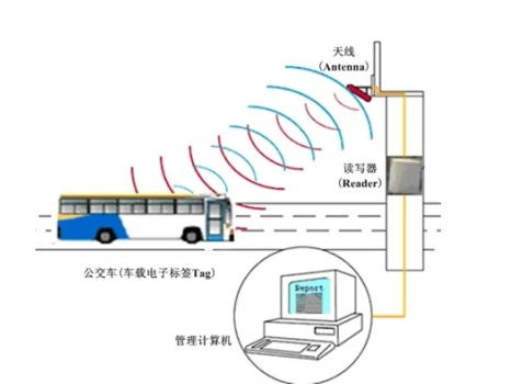
The overall system design system consists of a voice module, a single-chip microcomputer and an RFID module. The system determines the location of the vehicle through RFID, transmits the signal to the single-chip microcomputer through the wireless module, and then reports the station by the voice module.
2.1 RFID site identification module
This module realizes the function of RFID electronic tag identification and acquisition of relevant information at bus stations. Register at each bus station electronic tag. Due to the uniqueness of the RFID tag, the system can accurately identify and report the station after identifying the station. Through the identification of the electronic tag code, the station information is acquired and finally sent to the RFID station module.
2.2 RFID Report Station Module
After receiving the information sent from the bus station, it compares whether the station is a station on the bus line, obtains the information of the relevant station from the system, sends a signal to the voice broadcast system after confirmation, and the voice module plays the sound.
3、System hardware structure principle:
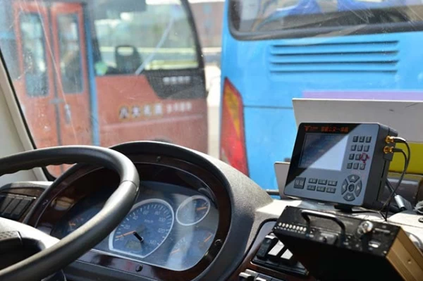
3.1 On-board hardware
The vehicle-mounted device is composed of a voice power amplifier circuit, a serial communication interface, a radio frequency transceiver circuit, a temperature and humidity measurement module, and a voltage stabilization circuit. The temperature and humidity measurement module uses the single-bus digital temperature sensor DS18B20 (temperature measurement range -55 to +125 degrees Celsius) to measure the temperature inside the car; the humidity sensor CHR01 measures the humidity inside the car; the infrared module detects the number of people getting on and off to get the total number of passengers.
3.2 Platform-side hardware
The station-side hardware is mainly composed of an encoding control circuit, an LED electronic circuit, a radio frequency transceiver circuit, and a voltage stabilization circuit. The radio frequency transceiver circuit sends electronic tag information and receives vehicle transmission information; the LED electronic circuit displays the information sent by the vehicle to the platform.
LED display: The LED display module uses 1602LCM character liquid crystal display. The 1602 LCD module's internal character generation memory (CGROM) has stored 160 different dot matrix character graphics. These characters are: Arabic numerals, uppercase and lowercase letters of the English alphabet, commonly used , And Japanese kana, each character has a fixed code.
4、System software structure principle:
The system software is written in C language. It can be divided into RFID electronic tag information, which is the parsed module to achieve information acquisition and identification functions; the bus status judgment module, and the corresponding execution program module to implement information processing and processing functions. LED display and voice output module realize information output function.
This is a simple flowchart for the acquisition and identification and implementation of RFID electronic tag information for buses. If no RFID signal is received or the electronic tag is "0000", no instructions will be executed. If an RFID signal is received, analyze whether the station belongs to the bus The planned route of the car, if yes, starts the voice chip reporting station; if not, no instruction is issued.
5、Conclusion:
According to the design scheme of this article, the automatic station reporting and platform LED display functions were completed, and the bus reporting station system was successfully automated. The inaccuracy of the bus reporting station can be resolved, providing a reliable and cost-controlled bus for the bus system The multi-functional automatic station stop system can display the number of people in the car, temperature and humidity information on the platform in time. If the wireless network or wired network is further used to transmit the vehicle station data to the bus management department or the traffic command department, real-time monitoring of the bus operation status can be performed.